The structural analysis software RFEM 6 is the basis of a modular software system. The main program RFEM 6 is used to define structures, materials, and loads of planar and spatial structural systems consisting of plates, walls, shells, and members. The program also allows you to create combined structures as well as to model solid and contact elements.
RSTAB 9 is a powerful analysis and design software for 3D beam, frame, or truss structure calculations, reflecting the current state of the art and helping structural engineers meet requirements in modern civil engineering.
Do you often spend too long calculating cross-sections? Dlubal Software and the RSECTION stand-alone program facilitate your work by determining section properties of various cross-sections and performing a subsequent stress analysis.
Do you always know where the wind is blowing from? From the direction of innovation, of course! With RWIND 2, you have a program at your side that uses a digital wind tunnel for the numerical simulation of wind flows. The program simulates these flows around any building geometry and determines the wind loads on the surfaces.
Are you looking for an overview of snow load zones, wind zones, and seismic zones? Then you are in the right place. Use the Geo-Zone Tool to determine quickly and efficiently snow loads, wind speeds, and seismic data according to ASCE 7‑16 and other international standards.
Would you like to try out the capabilities of the Dlubal Software programs? You have the opportunity to do so! The free 90-day full version allows you to thoroughly test all our programs.
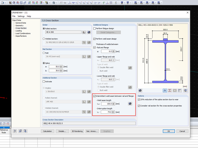
Yes, it is. The Intermittent weld seam option is suitable if the weld seam between the crane rail and the flange is not continuous. A parallel opposing arrangement is assumed. After you select the check box, you can specify the length of the weld seam and the interruption. These specifications are considered in the design.
On our website, you can also find an interesting technical article about "Ultimate Limit State Design of Rail Welds of Crane Girders According to EN 1993‑6".
When determining the punching load from shear forces in the critical perimeter, a continuous perimeter is applied.
If an intermittent perimeter was to be used when determining the punching load, the load component (along the intermittent length) might not be considered. This would be the case, for example, if you have only defined the opening in RF‑PUNCH Pro, but not in the RFEM model. In the RFEM model, the shear force would be generated using the continuous cross-section. If the component was to be neglected, an insufficient punching load would be determined.
Therefore, the intermittent control perimeter is always applied in RF‑PUNCH Pro when determining the punching load from the shear forces within the critical perimeter.
During the design (on the resistance side), the opening is considered again and the perimeter section is reduced accordingly.